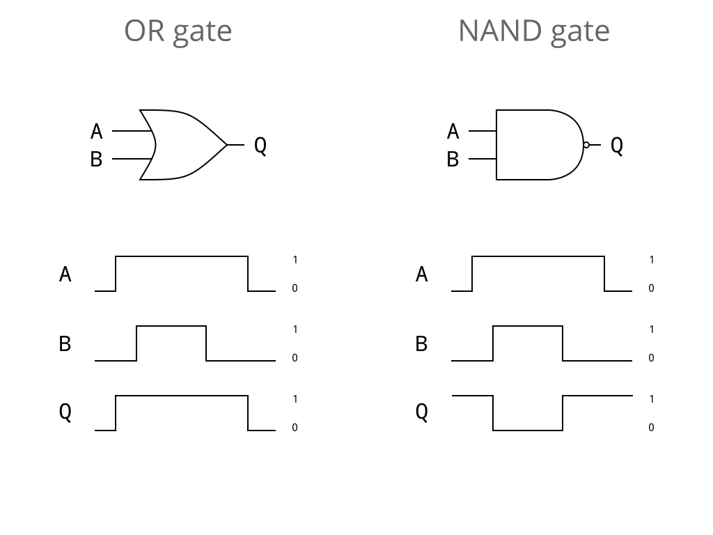
Combinatorial Logic
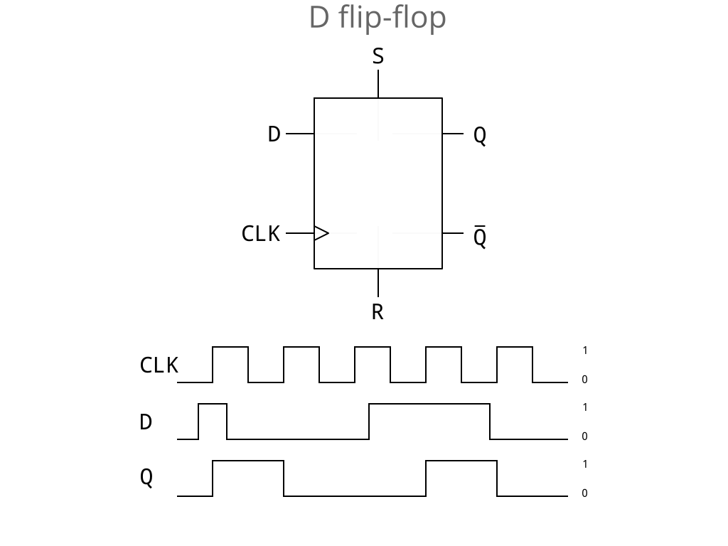
Sequential Logic
Register Transfer Logic
- registers: groups of flip-flops.
- nets networks of wires, connecting registers together
reg [31:0] program_counter
wire [7:0] bus
Verilog structure:
- modules to structure our design
- sequential logic to control how state moves between registers on clock edges
- combinatorial logic to link together nets continuously.
Modules
LED Module
Continuously assigns the value 1 to the LED pin:
module led (output led);

   led = 1;

endmodule
Module declaration:
- Input and output signals
- Items (internal wires / registers and logic)
Chip Module Example
Slightly more interesting module.
module chip (
    // 100MHz clock input
    input  clk,
    // SRAM Memory lines
    output [18:0] ADR,
    output [15:0] DAT,
    output RAMOE,
    output RAMWE,
    output RAMCS,
    // All PMOD outputs
    output [55:0] PMOD,
    input [1:0] BUT
  );
Combinatorial Verilog
Logic bitwise primitives, shifting
Negation
y = ~a;
AND, OR and exclusive-OR gates
y = a & b;
y = a | b;
y = a ^ b;
Arithmetic and logic shifts:
a           a >> 2      a >>> 2     a << 2      a <<< 3
01001111    00010011    00010011    00111100    00111100
11001111    00110011    11110011    00111100    00111100
Concatenation and Replication
wire y;
wire [1:0] y2;
wire [2:0] y3;

y2 = {a,b};            // creates a 2-bit signal of a with b
y2 = {a,1'b0};         // a with 1 bit binary 0 (constant)
y3 = {a,b,1'b1};       // a with b with binary 1 (constant)
y3 = {a,2'b10};        // a with 2 binary bits 1, 0
y3 = {a,a2};           // a with a2 (a2 is 2 bits)
y3 = {a,a2[0],1'b1};   // a with single bit from a2 with 1
If/Else
wire [7:0] a, b;
wire [7:0] min;

if(a < b)
   min = a;
else
   min = b;
Generally:
// need begin...end if >1 line of code within block
if(boolean) begin
  // if code
end else begin
  // else code
end
Combinatorial always blocks
Executed repeatedly depending on their timing controls.
always @(*) begin
  a = b;
  y = a | b;
end
For combinatorial logic, @(*): whenever an input changes.
Sequential Verilog
Sequential always blocks
always @(posedge clk)
   a <= b;
At the next positive edge of the clock, register a will acquire the value
held in b (which could be a register or wire).
Delayed (non-blocking) assignments
<= causes the value to be transferred on the next clock edge. It should
only be used in sequential always blocks.
Conversely = (aka blocking assignment) happens immediately and should only
be used in combinatorial always blocks.
This means you can do surprising things with registers:
always @(posedge clk)
   begin
      a <= b;
      b <= a;
   end
Verilog Summary
- C-like syntax
- “concurrent” semantics
- Modules provide reusable blocks of logic
- Combinatorial logic to compute binary functions
- Sequential logic for storage of values and clocked state update
Simulation
(Switch back to other slides)
Running example: counter.v
Interface:
module counter(
  input clock_i,
  input reset_i,
  input enable_i,
  output reg [7:0] count_o
);
- Takes a clock signal as input then counts.
count_oincremented every N clock ticks.
Getting started: top.v
module top(
  input        clock,
  input        reset,
  input        enable,
  output [7:0] count
);

  counter counter_i(
    .clock_i  (clock),
    .reset_i  (reset),
    .enable_i (enable),
    .count_o  (count)
  );

endmodule
Verilating: Makefile
Running Verilator:
verilator top.v counter.v
          --top-module top
          --cc
Compiling Verilator output:
make -C obj_dir
     -f Vtop.mk
     Vtop__ALL.a
     verilated.o
     verilated_vcd_c.o
Testbench: testbench.cpp
Instantiating the model, setting pin values:
Vtop *model = new Vtop;

model->reset = 1;
model->enable = 0;
clockModel();
model->reset = 0;
Clocking the model:
void clockModel()
{
  model->clock = 0;
  model->eval();
  model->clock = 1;
  model->eval();
}
Internal state: counter.v
reg [7:0] internal_count;

always @(posedge clock_i) begin

  if (internal_count == (CYCLES_PER_COUNT - 1)) begin
    // Increment external count if internal count rolls over
    count_o <= count_o + 1;
    internal_count <= 0;
  end else
    // Otherwise just increment the internal count
    internal_count <= internal_count + 1;

end
Reading internal state with a function
counter.v:
function [7:0] read_internal_counter;
  /* verilator public */
  begin
    read_internal_counter = internal_count;
  end
endfunction
testbench.cpp:
uint32_t internal = model->top->counter_i->read_internal_counter();
Modifying internal state with a task
counter.v:
task write_internal_counter;
  /* verilator public */
  input [7:0] new_internal_count;
  begin
    internal_count = new_internal_count;
  end
endtask
testbench.cpp:
model->top->counter_i->write_internal_counter(2);
model->eval();
Tracing: testbench.cpp
Trace file open / close:
VerilatedVcdC *traceFile = new VerilatedVcdC;
model->trace(traceFile, 99);
traceFile->open("model.vcd");

...

traceFile->close();
Tracefile dumping: testbench.cpp
vluint64_t simTime = 0;

void clockModel()
{
  model->clock = 0;
  model->eval();
  simTime += 5;
  traceFile->dump (simTime);
  model->clock = 1;
  model->eval();
  simTime += 5;
  traceFile->dump (simTime);
}
Viewing traces
Switch to GTKWave
Verilator Summary
Starting with a hardware model in Verilog
- Built software model with Verilator
- Driven the model with a C++ testbench
- Added functions to read internal state
- Added tasks to modify internal state
- Traced signals with Value Change Dumps + GTKWave